


Axis Conventions
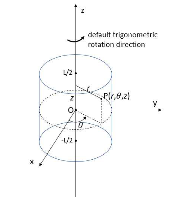
Default reference frame is the cylindrical frame (r,theta,z). The machine center is assumed to be at (0, 0, 0) and the 0z axis is the rotation axis of the machine (for both radial and axial flux machines). That way if the machine total length is L, it extends from Zmin= –L/2 to Zmax=+L/2.
Lamination axes (DQH)
In Pyleecan, we define DQH axis depending on their angle with respect to X axis. For instance the method comp_angle_d_axis will return the angle of D axis of a Lamination according to X axis.
By convention, the initial position of a Lamination is defined to have X axis at the middle of a tooth (inter-pole). The convention is used to provide a convenient default position to “cut” the lamination for FEA computation with symmetries.
For D/Q axis the following conventions are used for each lamination kind:
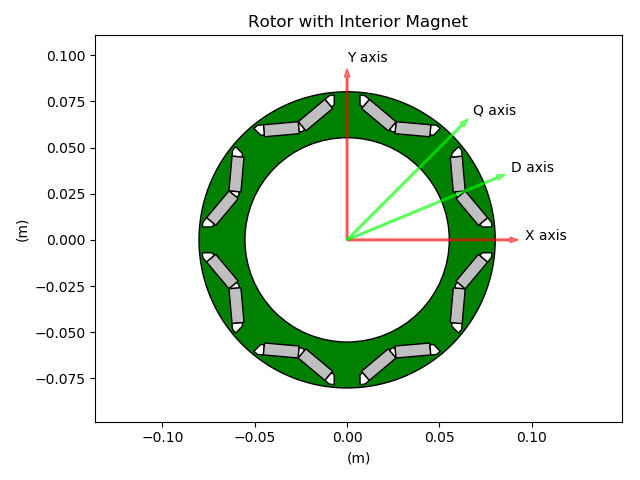
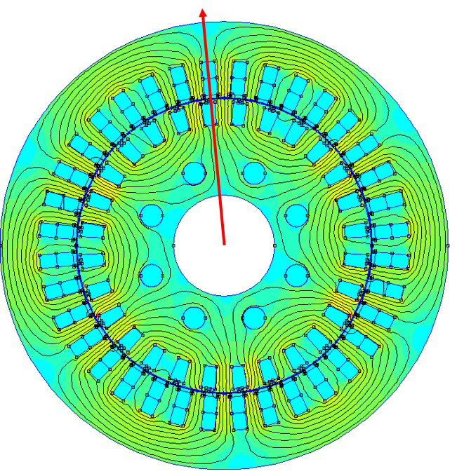
LamHole with magnets (IPMSM)
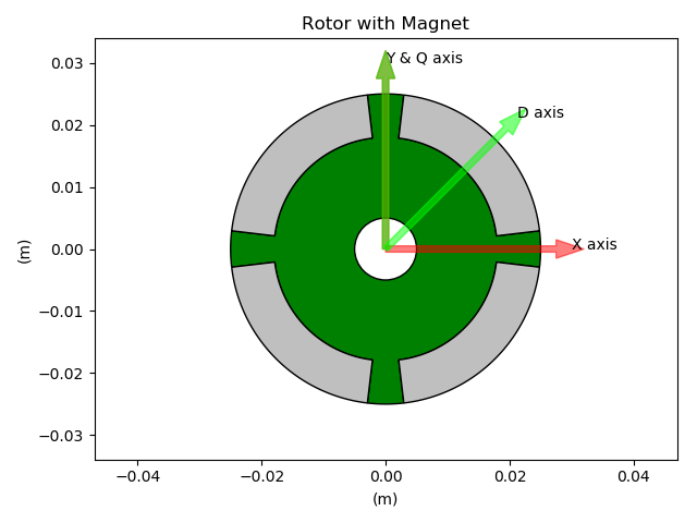
LamSlotMag (SPMSM)
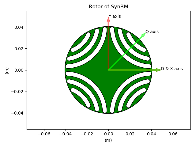
LamHole without magnets (SynRM)
LamSlotWind
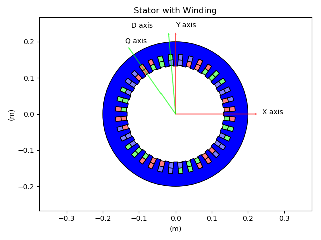
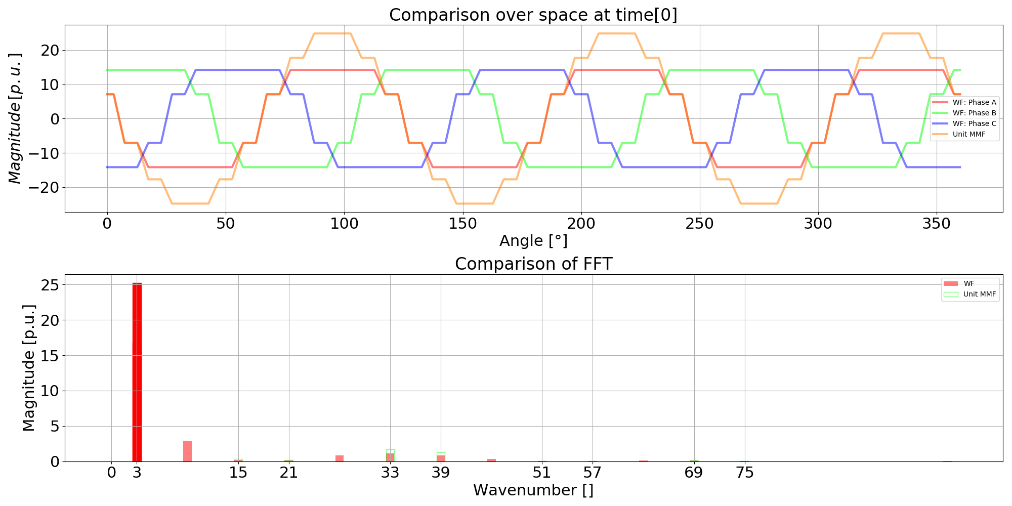
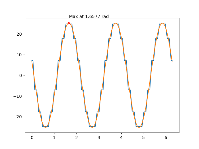
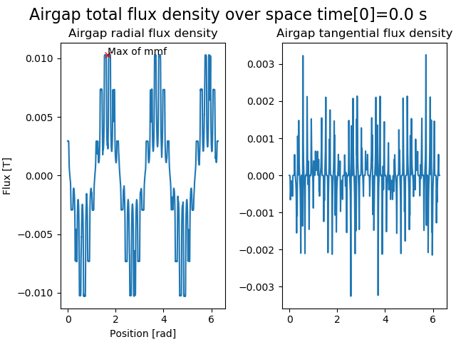
The LamSlotWind D axis is defined so its angle is the first angle where the fundamental of the unit mmf (and of the flux) is maximum at t=0. This definition also matches the alpha axis, since the first phase current has its maximum at t=0. The unit mmf computation follows the winding conventions and by definition LamSlotWind has evenly distributed slots.
This definition was set to enable to define the Machine method comp_angle_offset_initial (initial position of the rotor for electromagnetic computation). The inital rotor position is calculated as the difference between the D axis of both laminations whatever their type, i.e. stator D axis minus rotor D axis.
The code to reproduce all of these figures is available in Tests/Plot/test_axis.py